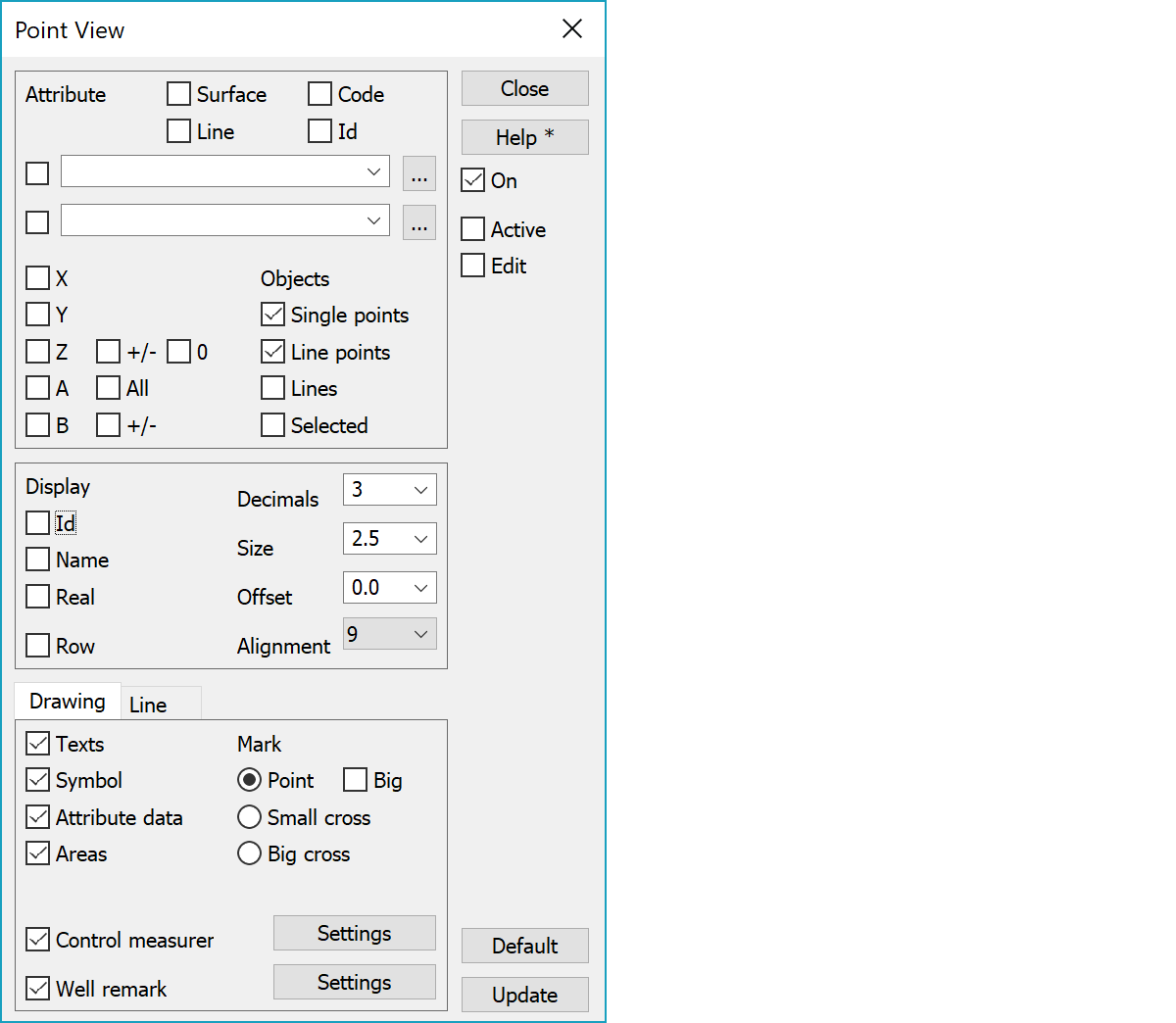
 Point view Point view
You can choose how individual points and lines appear on the screen. These settings can be set globally or separately for each file element.
Breakline and area info displaying depends on reference point definition. If the line or area has a defined reference point, information is displayed beside it just like for normal points. Otherwise the information is displayed beside the line in line direction and repeated every 100 meters. When zooming out in screen mode, longer interval is used so that texts do not overlap. However, information is always displayed at least once for every line. All line attributes and code fields, except the point number T4, can be displayed this way. For defined reference points coordinates can be displayed also.
Program recognizes contour line files calculated by itself and allows Z-coordinate display beside the line for them. Additionally, these values are always displayed in slope direction.
Beside the point you can put one or more attributes or coordinates. The points codes are written to the right side of the point. Line codes are written either between first two points or to the weight center, if defined.
Attribute is either id of some attribute (for example DIA) or asterisk (*), which draws all point’s attributes. Use comma to separate attributes. Attribute fields can also contain macros, whose value is always calculated in real time (e.g. #SLOPE or #AREA).
Browse button opens attribute list editing by default. With the Shift-key attribute in field is automatically added to the list. Accepting list with the OK-button sets selected line to the attribute field. If the field originally ended with comma, selected line is appended to previous value and new comma is added to end.
If the attribute field has no more than one attribute, browse with Ctrl-key opens value formatting. Multiple value formatting divides values first to a list from where the value can be selected for formatting. Browse with the Alt-key gets all attributes from active file objects as as a comma separated list. If the Ctrl-key is also used, only active point or line attributes are added to list.
A is a section number for bore, road, profile and cross section points. B is distance from centerline. Setting All beside the A-setting shows value also for measurement line breakpoints and vector file points. Vector file point A- and B-measurements are searched from attributes CRD_A and CRD_B calculated by calculation functions.
Use +/- options to get sign for Z- or B-values. Use 0-option to show also Z-values with zero height (0.0).
If Point View is selected On and some of the code fields (T1-T4), coordinates (XYZAB) or attribute data is selected, variables for a certain symbol are not shown with the symbol. E.g. if a fixed point has a symbol to show also point number and height, these will not be shown if Point info has code fields selected On, because the values might overlap each other in the screen.
Cross section and profile windows have special functions to show additional information.
The settings in this dialog can affect single points, line info or line points.
Settings are used only for selected points. You can force this On in the Program startup -settings.
Determines format of the text. Id is code field, coordinate or attribute identifier (for example T3, X or DIA) and name is its real name according to the code file (for example Class or Diameter). Real determines for code fields and indexed attributes if the index or the real value from the code file is drawn. If all three boxes are checked, the result might look like following: MAT=Material=Concrete or T3=Class=Traffic sign.
Stores comma separated codes as a one single line text.
Number of decimals displayed in coordinates. Negative value can be used for rounding to nearest power of ten (-1 = round to 10, -2 = round to 100).
Text size and offset. Positive value is in millimeters and negative value in meters. This size is also for printing. If you want bigger text only in screen, use text scale in window settings. Offset moves text always away from the point and has no effect with centered alignments 5 and 11. With alignment values 2, 8 and 14 offset movement is vertical. All other alignments use horizontal offset.
Text alignment position according following picture:
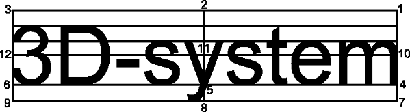
Value 14 draws text vertically. Value 15 means single line numeric value alignment to the decimal point. This works in screen and printing, but is converted to value 5, when transferred to other systems.
Determines if texts are drawn.
Determines if symbols and line types defined in code file are drawn.
Determines if object’s attributes are used for symbol size and line width calculation.
Determines if areas are rasterized according to code file definitions.
Point size on screen. Point is either one pixel or 3x3 pixel cross, if the Big option is on. Bigger point is more visible in high-resolution displays. Small cross size id 5x5 pixels and big cross size is 9x9 pixels. Marked and active point are displayed using the big cross size.
Toggles control measurement arrow painting on or off. Settings button opens control measurement settings.
Toggles well remark attribute drawing on or off. Settings button opens well remark settings.
Labels are drawn only when this setting is on. Function toolbar button with the Ctrl-key turns setting on or off without opening dialog. There is also a special function to set the checkbox on or off. You can force this Off in Program startup -settings.
Point view settings are used only for active file or edited object (point, line, area). These settigns are always automatically turned off after the program is started.
Restores function default values.
Updates screen with new settings.
If the total point amount in visible element list files is less than the value given in the file settings, the screen is updated automatically after after checkbox and list selection changes. Update can also be forced by holding down Alt-key.
There are some special settings related to this function.
A comma separated list of decimals in selection list.
A comma separated list of text sizes in selection list.
A comma separated list of offsets in selection list.
If 1 (default), does not draw symbol texts (e.g. T4, Z) when the point label drawing is on. This is to prevent drawing point and symbol labels over each other.
See also: Using special settings