 Settings Settings
Use settings to define how the differences are shown in the screen. All tabs have same settings and they can be controlled separately. By using them it is possible, for example, display XY- and Z-errors with different settings. For used settings, tab title displays values of XYZ-settings (e.g. 1 XY or 2 Z).
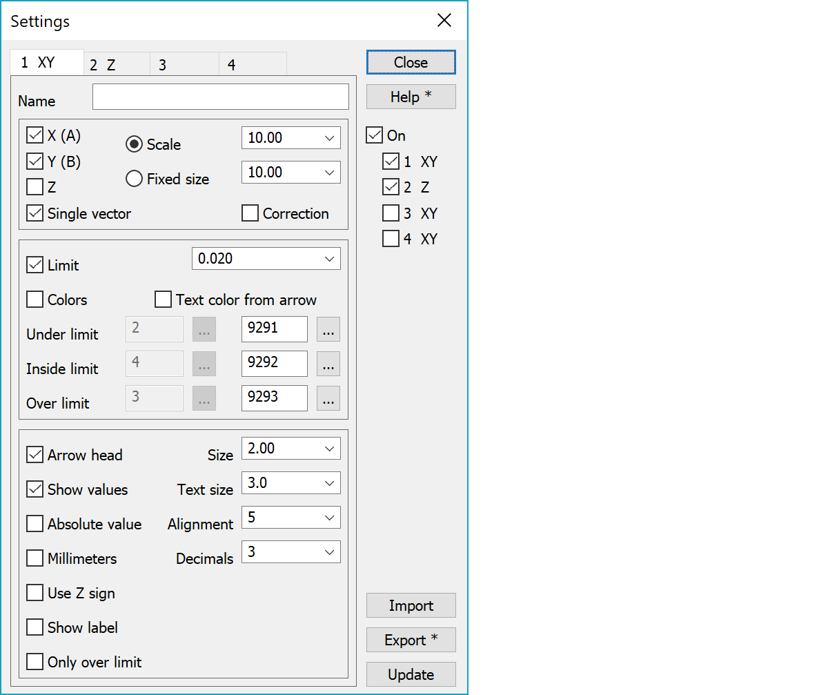
Settings name.
Arrow and value label drawing selection. X-, Y- and Z-settings define which differences affect drawing. If the Single vector setting is off, each dimension has separate arrow drawn its own axis direction. If the Single vector setting is on, selected dimensions are combined to the single error vector.
There are two ways of displaying the Z-vector from above. If Single vector setting is off, the Z-vector is drawn in 45 degree angle between X- and Y-axis. If Single vector setting and Z-setting alone are on, the Z-vector is drawn vertically up or down depending its sign. In three dimensional view the Z-vector is drawn normally its own axis direction.
Scale rescales the difference vectors in the screen with given multiplier. Fixed size uses same size for all vectors. Negative fixed size is in meters and positive in millimeters.
Error vector can be drawn either as error or correction. This will swap the sign and direction of error vector.
If this is selected, unsigned error values greater than limit are displayed with different color. If the limit value is 0.0, negative components are drawn with the first color and positive ones with the third color. You can also give two comma separated values, who define lower and upper tolerance limit separately. The second color is then used for values between lower and upper limit.
Limit values can be asked with macros in title files and format converter header files. If the Single vector setting is on, macros return only given maximum tolerance value. Otherwise single component macros return separately lower and upper tolerance values. Returned values are either meters or millimeters according to the Millimeters setting. Macro values are searched from all active tabs and first value matching to macro is returned.
Define either three colors or three codes to be used for error vectors. If the color checkbox is checked, color from color table will be used. Otherwise code file codes are used. Picture files use always codes. Texts are black by default, but can be changed to use arrow color with a checkbox. If you have defined a specific color for any file in Element settings, this color will be used also for the error vectors.
Arrow endpoint will be drawn, if this check box is selected. Select the arrow size from the list. Positive value is size in millimeters and negative value is size in meters.
If this is selected, the difference value (dx,dy,dz or dxyz) is shown.
Text appearance is defined by the code file font list code 9290. If the font has size 0.0, point view text size is used. If the the font definition has color 0, arrow color is used for value label. Otherwise the font color is used. If the text size setting is not zero, it is used for text size.
Values are displayed without sign.
Value text alignment around the arrow tip. Zero is automatic alignment based on the arrow direction.
Values are displayed as millimeters (multiplied by 1000). Amount of decimals is stored separately for meters and millimeters.
Uses Z-component sign for combined error vector sign. Affects both error value label display and limit checking.
Displays label in front of the value.
Displays only arrows with values over the limit.
Settings are used only, if this checkbox is selected. Press Ctrl+Settings to set On-selection On/Off without opening the dialog. With checkboxes 1 - 4 each setting tab can be controlled separately.
Settings can be written to a file and read back from it. By default, all settings are written to file. With the Alt-key only active tab setting are written. Import recognizes automatically if the file has one or all settings.
Redraw screen with updated values without closing the dialog.
If the total point amount in visible element list files is less than the value given in the file settings, the screen is updated automatically after after checkbox and list selection changes.
There are some special settings related to this function.
Default values for the arrow size in selection list.
Default values for the number of decimals in selection list.
Default values for the limit values in selection list.
Default values for the scale factors in selection list.
Default values for the constant size in selection list.
Labels used for controls, XYZABZd by default. First three letters are labels for controls relative for coordinate axis (default XYZ) and following three letters are used for controls relative to reference line (default ABZ). Last letter is optional prefix for labels (default d).
See also: Using special settings