 Vertical alignment window settings Vertical alignment window settings
Drawing settings for the vertical alignment window.
Additional data below profile (profile data, etc) is drawn outside actual coordinate area and they need to have separately reserved space in the title file. This can be done by recucing the size of the CLR-area which defines the coordinate axis positions.
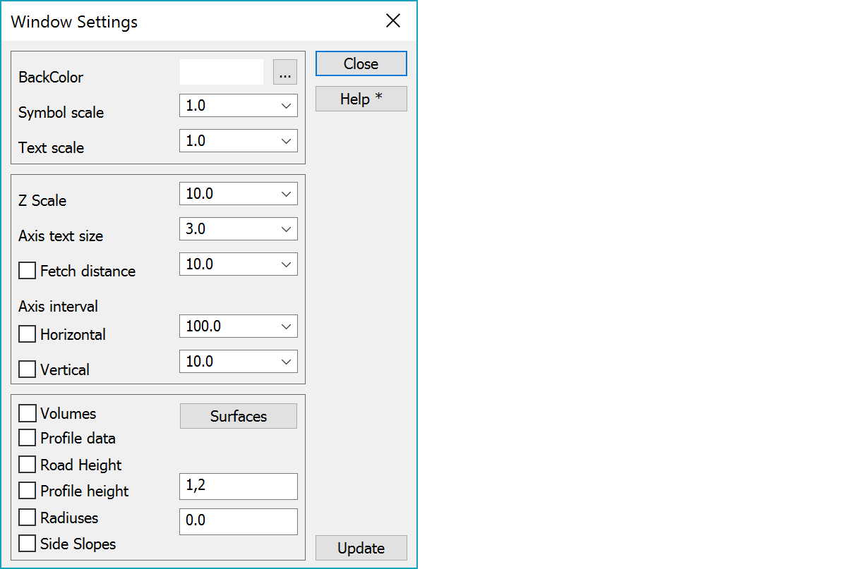
Background color can be chosen from the Windows color palette. Other colors that the program uses can be chosen in Settings/Code file.
If you set black color as the background color, the other windows will get the same background color. When printing to paper a white background will be used automatically. Color 1 in color table will be changed automatically, if it is same as background color. There is also shortcut key F12 for quickly cycling through black, white and user background color.
In Element settings you can define default color for file elements using Shift-color button.
Scale factors for symbols and texts affect their appearance on screen only, not on paper. This is usually done to improve the clarity while editing data by making them bigger.
Height scale multipler to normal scale defined in paper settings.
Text size in millimeters for horizontal and vertical axis.
The distance how far program tries to find additional drawing elements. From main window bore files all soundings inside the given distance are fetched. With distance value zero only intersecting line positions are shown. Checkbox turns point fetching on.
If the checkbox is On axis spacing will be locked to the given value. Otherwise the spacing will alter according to window (or paper) size.
If you input negative value for spacing, no lines are drawn. Tick marks and value are written normally.
Zero axis width can be increased by changing the system code 9090 line width.
Showing volumes in profile.
Volume calculation for cross sections stores the calculated volumes in the cross section file. These can be used in vertical geometry window. The volumes are read from the file and drawn into screen as volumes lines. Surfaces -button open a list, where you can select the volumes to be drawn. Button also displays amount of selected surfaces in parenthesis.
To show attribute data related to a cross section.
To show the height of vertical geometry in the picture.
To show the height of given surface in the picture. You have to read the profile with surface in the main window.
To show radiuses in the picture. Input a value to be used for rescaling the radiuses.
To show side slopes in the picture.
Updates screen with new settings. The screen is updated automatically after after checkbox and list selection changes.
See also: Cross section and profile window drawing
There are some special settings related to this function.
The text size of additional information (profile data, road height) in vertical alignment window compared to axis text size. Default 0.75 gives a bit smaller text than the axis text.
See also: Using special settings