 Cross section window settings Cross section window settings
Settings for the cross section window.
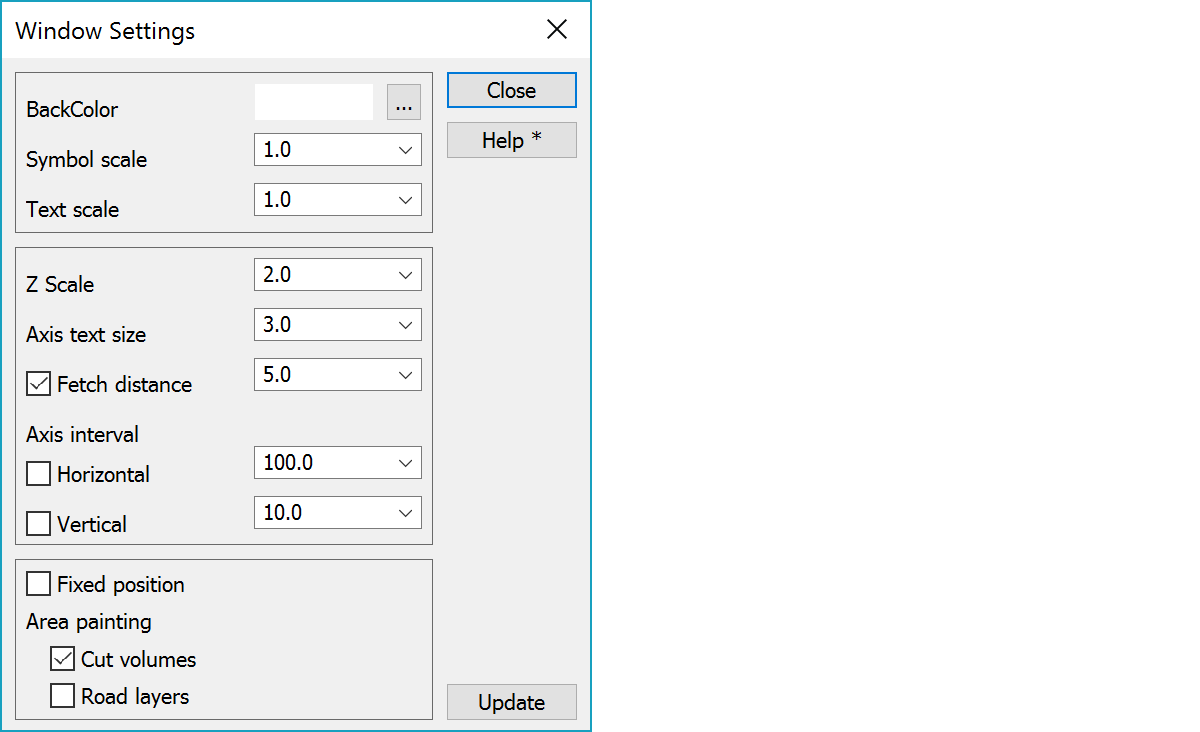
Background color can be chosen from the Windows color palette. Other colors that the program uses can be chosen in Settings/Code file.
If you set black color as the background color, the other windows will get the same background color. When printing to paper a white background will be used automatically. Color 1 in color table will be changed automatically, if it is same as background color. There is also shortcut key F12 for quickly cycling through black, white and user background color.
In Element settings you can define default color for file elements using Shift-color button.
Scale factors for symbols and texts affect their appearance on screen only, not on paper. This is usually done to improve the clarity while editing data by making them bigger.
Height scale multipler to normal scale defined in paper settings.
Text size in millimeters for horizontal and vertical axis.
The distance how far program tries to find additional drawing elements. From main window bore files all soundings inside the given distance are fetched. With distance value zero only intersecting line positions are shown. Checkbox turns point fetching on.
If the checkbox is On axis spacing will be locked to the given value. Otherwise the spacing will alter according to window (or paper) size.
If you input negative value for spacing, no lines are drawn. Tick marks and value are written normally.
Zero axis width can be increased by changing the system code 9090 line width.
You can choose to have a constant position for cross sections when moving forward or backward. If this checkbox is On the cross section’s middle point (in height) is always in the center of the window, otherwise the positioning is checked individually for all cross sections. Use Fixed height especially for serial output to ensure all cross sections have the same appearance on paper.
To control which areas are filled in volume calculation. ‘Cut volumes’ colors only soil surfaces and ‘Road layers’ colors all construction fill surfaces. The latter is always colored last (on top of the first). Colors used can be defined in code file.
Updates screen with new settings. The screen is updated automatically after after checkbox and list selection changes.
See also: Cross section and profile window drawing
There are some special settings related to this function.
Attribute name for diameter. Used to draw diameters for pipes and wells in cross sections.
Attribute name for depth. Used to draw depths for wells in cross sections.
Attribute name for height. Used to draw heights for district heating pipes in cross sections.
Attribute name for width. Used to draw widths for district heating pipes in cross sections.
Attribute name for protection area. Used to draw protection areas for pipes in cross sections.
Attribute scale for each attribute above respectively.
Text size of additional (profile data, center line height) information compared to axis text size. Default 0.75 is little smaller than axis text size.
List of surface codes behaving like surface 9 in cross section windows. These will use code file cross section symbols and possibly size defined by line attribute data. By default, InfraBIM pipe networks (1431??,1435??,3?????).
Cross section position line tick mark interval in meters.
See also: Using special settings