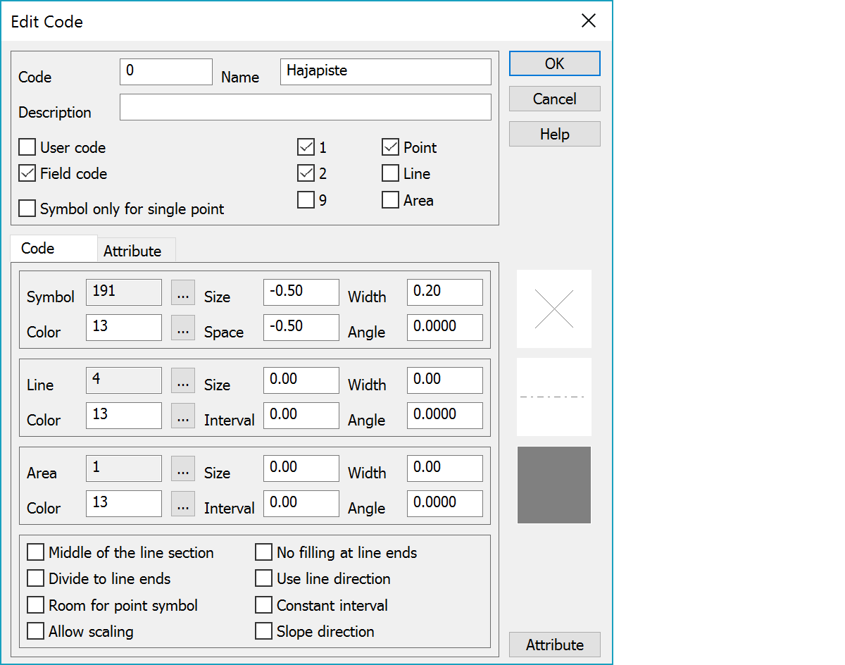
Defining the code’s code name, symbol and line type to the code fields. Width and size values are in millimeters (positive values) or metric (negative values). Size in millimeters will always be the given value, whereas sizes given as metric, are scaled according to the output scale.
Id used for refrencing and user defined descriptive name for the code.
For T1-code field you may enter two names separated by a semicolon. The first name will be used in normal lists and showing point info. The second one is used in volume calculation report file for different soil types. E.g. surface 11 is normally ‘Lowest construction surface’ but in volume calculation ‘Fill’ or ‘Bank’.
Longer description for code.
Settings can be used to limit code list exporting only for user's own codes or field codes.
Symbol definition is not used for line drawing.
Surfaces allowed for the code. In no surface is defined, all are considered allowed. Used in the file check. Do not otherwise affect the use of codes in progam.
Types allowed for the code. In no type is defined, all are considered allowed. Used in the file check. Do not otherwise affect the use of codes in progam.
Point symbol used for a code. Code can have two symbols separated by colon (e.g. 180:181). By default the symbol button is used to select single symbol. With the Shift-key the start symbol can be selected and with the Ctrl-key end symbol is selected. By default two symbols are drawn to same position using same settings. If symbol drawing settings defines symbol division to line ends, start symbol is drawn to the beginning of the line and end symbol to the end of the line.
Color used for drawing. Can be given either as a color table index 1-30 or as a real RGB value. The browse button opens either color table or RGB selection depending on the field value. With the Shift-key browsing can be forced to the RGB selection or with the Ctrl-key to the color table.
Symbol size. Positive value is in millimeters and negative value in meters.
Space reserved for symbol in the line. Positive value is in millimeters and negative value in meters.
Line width used in drawing. Positive value is in millimeters and negative value in meters. Width 0 is drawn with the thinnest possible one pixel line.
Symbol angle.
Line type used for a code. The size and interval given here affect symbol line drawing, which is done by copying selected symbol in given intervals. If the Point view settings have the minimum line width defined, the line is drawn using at least that width.
Area rasterization type used for a code. Default type for rasterizing is diagonal cross (XXXX). This is used for areas which have no raster type defined in code.dat-file. Special types 8 and 9 can be used to create totally transparent or current background color areas.
Area rasterizations 2-7 are drawn either as vector lines or using Windows standard hatches. If the Interval setting has non-zero value, vector drawing is used. Interval setting defines then line interval and Width setting individual line width. Both can be given as positive millimeters or negative meters. If the Interval setting value is zero, Windows standard hatches are used. Their size is not affected by any setting.
Vector line rasterization position can be changed by giving offset parameter in Size setting. Rasterization starting point is moved by the given value. This makes areas using same rasterization type visible on top of each other.
It is also possible to use raster bitmaps for area painting. In addition to the basic raster hatch types, the area type list displays also all BMP raster file names from the [user]/Symbol directory. These small bitmap files are used as mosaic tiles for area filling. They are not transparent and will cover all objects below them. The area color setting can be used to change the color of black pixels, but other settings have no effect on them.
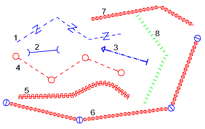
Numbers in parenthesis at the end of descriptions refer to example picture at the end of the page.
Point symbol is drawn at the middle of the line section instead of breakpoint. If the point has two symbols, first is drawn to the breakpoint and the second to the middle of the line section. (1)
Point symbol is divided from middle and two halves are drawn at the endpoints of the line. If the point has two symbols, first is drawn to the beginning of the line and second to the end of the line. (2, 3)
Line symbol drawing is started and ended from distance to breakpoint determined by the space reserved for the point symbol. (4, 6)
Line symbol is scaled so, that they fill exactly the space between breakpoints. (5, 6)
If the line symbol is not scaled, program fills the remaining space with line to breakpoint (7). This setting prevents that filling (8).
Point symbols are rotated to line direction. (1, 6)
Point symbols are positioned by constant interval defined by the point space. Position is calculated either along the breakline or along the horizontal axis for profiles. If the Middle of the line section setting is on, the symbol is draw at the middle of the nearest point interval. If the point has two symbols, first is drawn to the breakpoint and the second using constant interval.
The direction of symbols between line points is determined by the height difference.
Editing the attribute list. Attribute definitions support code wildcards. For example, attributes defined for code 3???? can be used by all five number length codes starting with number three.