 3D-orthogonal calculation 3D-orthogonal calculation
Three dimensional AB-calculation. Select first two points (P1 and P2) for the reference line. Then you can either select other points and get the calculated values in dialog and result file, or type in values in the dialog and get new coordinates.
General principles how the calculations work are explained under Calculation functions.
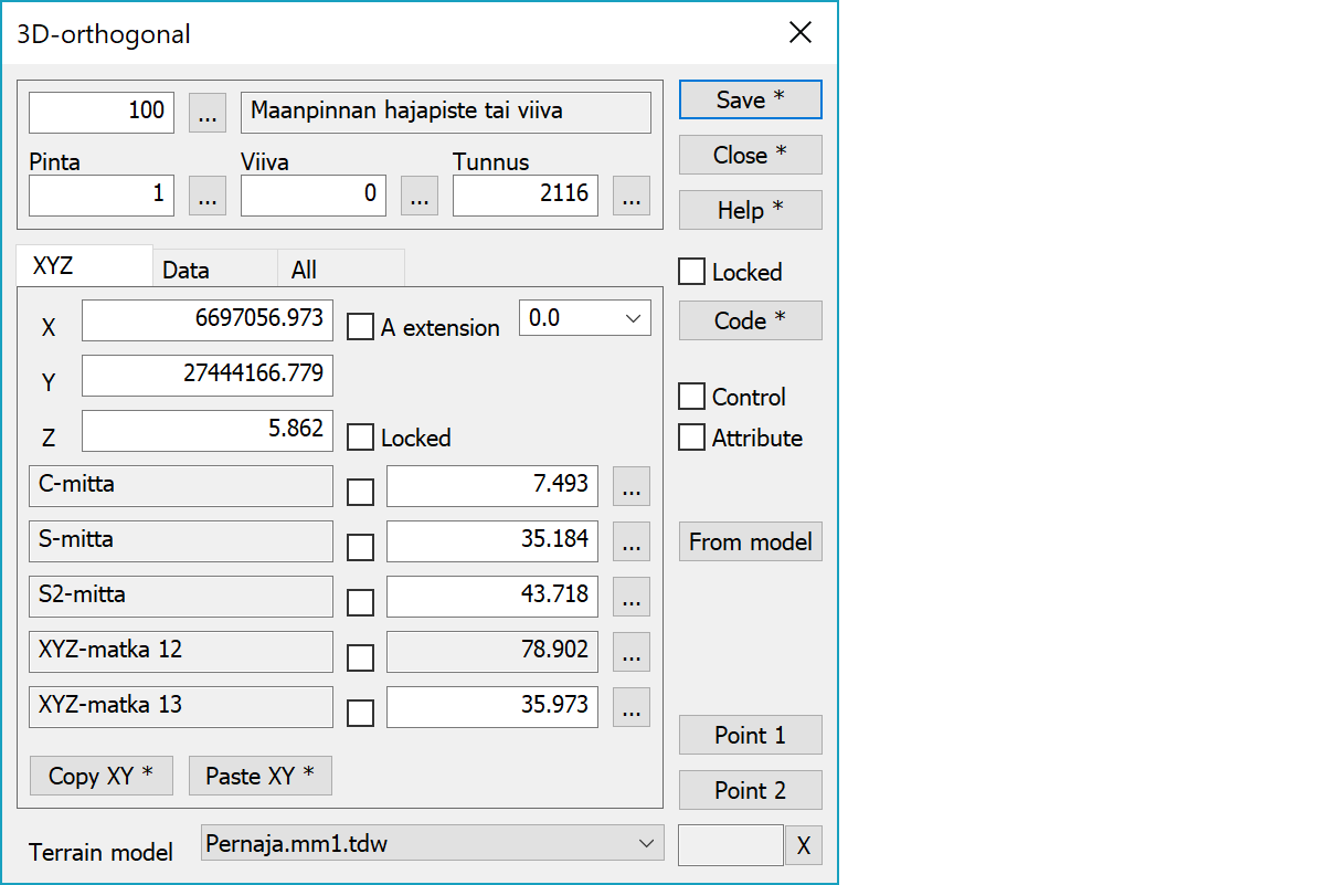
Upper part fields display object type and three freely selectable attributes.
Point coordinates.
Warning from calculation outside of reference line. Value is allowed extension and if point is beyond it, field backgroud color changes to red.
Any single calculation paramater can be locked in calculation.
Five selected calculation parameters and their values. Parameters that cannot be edited are grayed.
Copies coordinates to the clipboard as a comma separated text. By default copies only X and Y. With the Shift-key the Z is also copied. With the Ctrl-key XY-coordinate order is swapped. With the Alt-key decimal separator comes from system settings and field separator is tabulator. This format can be pasted directly to Excel columns as numeric values.
Pastes quote, semicolon, tabulator, space or linefeed separated coordinates from the clipboard to the coordinate fields. If the clipboard data contains decimal points, comma is also handled as a field separator. Otherwise comman is handled as a decimal separator. Paste works also directly with columns copied from Excel. With the Ctrl-key XY-coordinate order is swapped.
Saves the current point. With the Alt-key modifies active point instead of adding new point.
Locks code fields. Pointing points with mouse gets then only coordinates. Locked codes are saved at exit and restored when function is started.
Activates the data copying from another object. The other object containing data is pointed by the mouse. By default only the object code is copied. With the Shift-key all attributes are copied including the line number. New points are then added to that line.
Saves difference values as control attributes to original points. Control arrows are then drawn according the control measurement settings.
When the checkbox is selected, calculation results are stored to both selected and created points as attributes. Calculation result attribute names can be found from the calculation parameter list.
You’ll get the intersection point of the reference line and the model. Dialog values will be updated. In case of several intersection points, the one closest to point P1 is selected.
You can change the reference line by pressing the button Point 1 and then using mouse to select new start and end points. If you press the button Point 2, you can change only the end point.
Select the model to be used in calculation.
Displays current edit mode (move, rotate, add, etc.). The X button quits the mode and returns to the normal state.
CheckDuplicate special setting in Settings/Start Program defines whether active file is checked for duplicate points.
There are some special settings related to this function.
Settings affecting edit and calculation function behavior.
Defines which attributes are displayed first in the list. By default T1,T2,T3,T4,T5.
See also: Using special settings