 Triangulation Triangulation
The terrain model is formed by triangulation. You can triangulate the whole active element (Automatic file selection) or just selected points in a group. The terrain model created by the triangulation will be stored to its own file using default 3D model file extension.
Before the triangulation some checks are made to the file using same method as in file check, but with its own separate settings. Arcs are checked always and the triangulation maximum side length is used as a maximum line section length. All other checks and limits can be defined by the user. If checking finds any errors, their amount is displayed by type. If there were no arcs, it is possible to continue to triangulation after confirmation.
At least crossing breaklines must be fixed and possible arcs divided to breaklines.
After the triangulation separate areas and possible holes inside them are searched from the model. If there are more than one area or there are holes inside areas, warning is given. Areas and holes can then be viewed with separate function.
Created terrain model Triangulation can also be saved as a DXF surface model using File/Formats/Write.
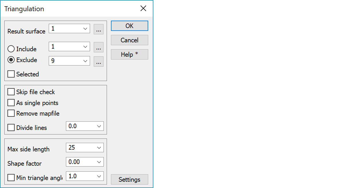
The surface code of the resulting square net. The default value is the first point surface code, which is not 9. If this is not found, 1 is used as a default. Otherwise, the original data surface codes are not important. The created terrain model is named by using this code. The given surface code is used later e.g. in volume calculations. The surface code can be chosen from the list or given by hand. The browse button opens the code file surface list for selection.
You can choose what surface codes are included or excluded. E.g. points with surface code 9, which are not normally included in the terrain model, can automatically, be either included or excluded from the triangulating. If you use the Include option, changing the result surface will automatically update the Include field. Several surface codes can be included or excluded by separating them with comma. Browse buttons open the code file surface list for selection.
Triangulates the selected points from all the files. If the checkbox is unchecked, the active element will be triangulated. Above Include/Exclude settings is also still used.
Skips file checking before triangulation. This setting is automatically turned off at program startup.
The selected data (active file or selected points) will be handled as single points. Break lines are converted into single points before triangulation. This will not affect the original data. One point lines are always converted into single points automatically.
Single point triangulation skips all code checks in the pre-triangulation file checking. This setting is automatically turned off at program startup.
Remove mapfile (the active file) when points have been copied to the terrain model. This saves memory when triangulating big files. Can not be used with Selected checked.
Divide break lines using given maximum length. Every section of the line is divided into equal length lines which are all shorter than given maximum length.
The most common reason to crash the triangulation is to have long break line sections and single points very close to these lines (few centimeters). Dividing break lines will solve most problems. Use 4-10 meters in normal cases.
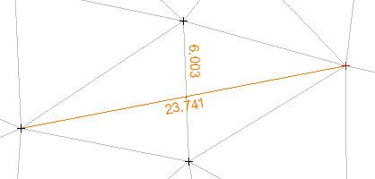
The length of the triangle side can be limited. You can choose the length from the list or give it by hand. Side length can be changed later in model editing. This setting is used automatically as a maximum line section length in the pre-triangulation checking.
Swaps adjacent triangles in the network based on three rules: shorter diagonal of the quadrilateral formed by two adjacent triangles, relatively wider triangles from all possibilities and finally swapping triangles away from same breakline. The function parameter is minimum acceptable value for half of the shorter diagonal divided by the longer diagonal. For symmetrical triangles this is triangle height divided by its base length.
Shape factor value 0.0 selects always shorter triangle side. Value 1.0 tries to make triangles as equal sided as possible to avoid very narrow triangles. Usually value 0.0, which uses Delauney algorithm, works well with normal terrain models.
The program marks hidden all the edge triangles that have an angle smaller than this.
Settings for pre-triangulation file checking.
There are some special settings related to this function.
A comma separated list of side lengths in selection list.
A comma separated list of surface codes in result surface list.
A semicolon separated list of surface codes in include selection list.
A semicolon separated list of surface codes in exclude selection list.
A comma separated list of minimum angle values in selection list.
A comma separated list of swap triangle values in selection list.
See also: Using special settings