 Edit vertical alignment Edit vertical alignment
A new vertical alignment is created by selecting first Add-function and pointing with mouse the center line of the road as a break line. To edit the horizontal alignment, select one point using method Point to active a segment and to edit the parameters. The active alignment and the segment are shown using predefined editing colors.
The vertical alignment is stored in the same file element as horizontal alignment in 3D binary format.
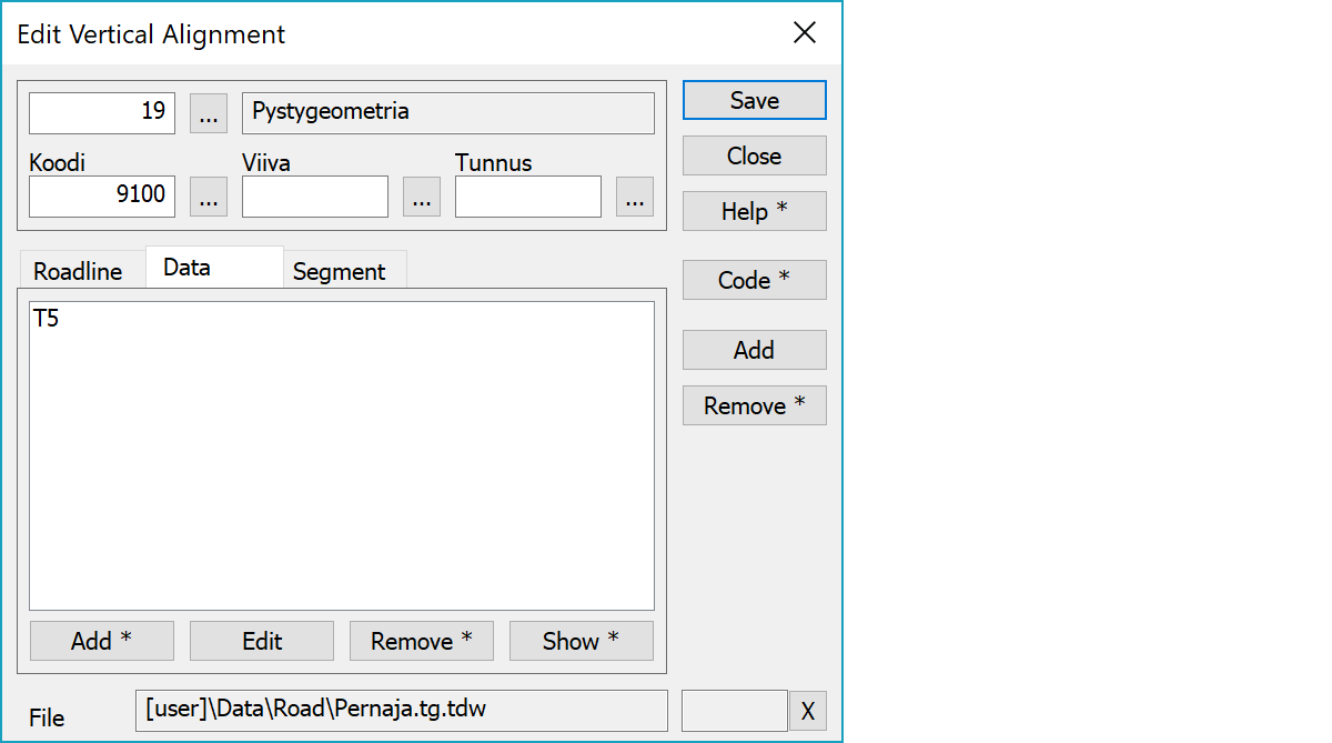
Upper part fields display object type and three freely selectable attributes.
List of object attributes not displayed in the above fields.
Activates data copying from another object. Method Nearest point copies data from the nearest point and method Mouse from the nearest line. By default only the object code is copied. With the Shift-key all attributes are copied.
A new arc segment will be added every time you use mouse. The new segment becomes active and radius will be set to zero. You can add new segments either in the middle of the road or at the end.
Deletes the active segment. With the Shift-key asks confirmation and clears whole vertical alignment.
The file element where the object belongs.
Displays current edit mode (move, rotate, add, etc.). The X button quits the edit mode and returns to the normal state. If no mode is active, it releases the current object.
There are some special settings related to this function.
Settings affecting edit and calculation function behavior.
Defines which attributes are displayed first in the list. By default T1,T2,T3,T4,T5.
See also: Using special settings