 Edit line Edit line
Editing a line. The line is activated by pointing it with the mouse and the closest line section is marked as an active section. If the line is pointed outside of its edpoints, only the endpoint is activated. The active line is displayed with an edit color. The beginning and the end of the line are shown with ortogonal line symbols. Also possible arc radiuses and hidden line sections of the active line are displayed. Additionally, currently active line section is shown with a different color and small arrow pointing the line direction. The active point is the endpoint of the active section.
Line reference point is a location where line attributes are shown. If it is not defined, location halfway between first two line points is used by default. Reference point is not normally displayed and it cannot be picked by mouse. When editing line, it is displayed as a small circle and its location can be changed by tools in Reference tab page.
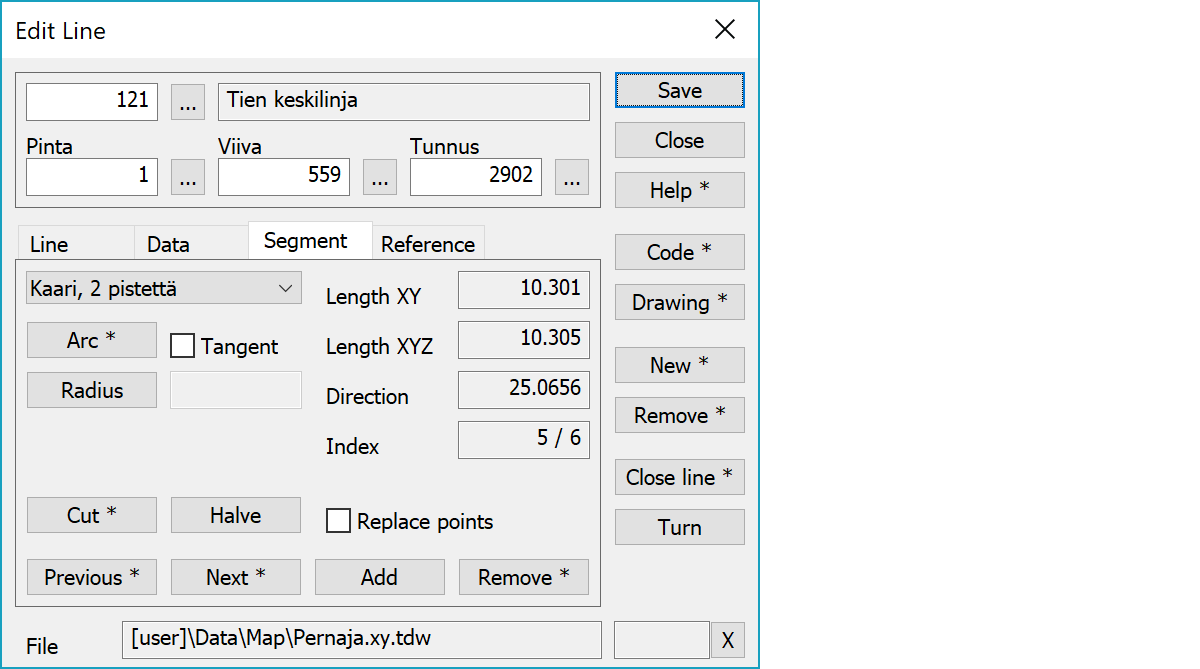
Upper part fields display object type and three freely selectable attributes.
The arc button creates new arc or circle using currently active line points. The creation method is selected from the list above. The current line must contain enough points for the selected method. Points used for arc are currently active line point and its previous points. Arc creation can be used during point adding by first adding required points to the line and the pressing the Arc button. Circle methods use always all active line points.
With the Shift-key arc rotation direction is changed. Alt-key with three point arc leaves the original middle point and creates arcs both sides of it.
Forces arc end tangents to match with the line direction by moving the endpoints.
Radius field displays current arc or circle radius. The Radius button activates the arc edit mode and the radius can be changed by pointing arc with mouse. When changing the radius of single arc, arc endpoints do not move. When changing the arc radius within breakline, arc endpoints move along the adjacent line sections.
The line will be cut in the place you have selected. A piece is ‘removed’ from the line. Fields and attributes will not be changed. If you hold down Shift-key while selecting Cut, the line will be cut at the active point (red cross), but no points are removed from the line.
With the Alt-key changes closed breakline closing point to the active line point.
New point is created in the middle of the active section.
With the Ctrl-key calculates new point as an intersection of adjacent sections and removes original section end points. Height of the intersection point is an average of heights calculated from original sections. Average calculation does not use zero heights. If the active section is arc in start or end of line, new point direction is calculated from arc end point tangent. Otherwise adjacent section directions are used for arcs also.
2D and 3D length of the line section and its direction in gons.
Index is active point index within the line. Additionally, the active point number is displayed at the upper part id field.
Move the active section back or forward. With the Shift-key line's first or last point is activated. Normally arc centerpoints are skipped, but with the Ctrl-key they also can be activated.
Activates the point adding. Following mouse clicks will add new points to the active line section or to the line end. Pointing existing points with the Closest point method copies them to the line by default. With the Replace points setting original point is removed. New line point is set automatically as an active point.
With the Shift-key starts densification, which adds new interpolated point to the line section in pointed location. Active line section is searched automatically using pointed location and after adding new point is active section endpoint.
Removes the active point. If the point is arc start or end, whole arc is removed. If the point belongs to the circle, whole circle is removed. With the Shift-key the point is converted to single point.
Activates data copying from another object. Method Nearest point copies data from the nearest point and method Mouse from the nearest line. By default only the object code is copied. With the Shift-key all attributes are copied. If the pointed object is line point, attributes are copied from line object.
Opens drawing data editing. Number of defined drawing data items is displayed in parenthesis after button label. With the Shift-key clears drawing data.
Creates new line and activates the point add mode. Each subsequent mouse click then adds new point to the line. With the Shift-key makes just a copy of the active line and activates the move mode.
If new line is created with method Breakline, undo removes whole line. Pointing the line with the Alt-key makes it possible to undo all added points separately.
The line and the points belonging to it are removed. With the Alt-key starts continuous remove mode. Objects pointed with the Alt-key are immediately removed.
The line’s direction is reversed. The direction of the line is sometimes important. In several mapping systems, slope marks/labels etc. are drawn in particular positions. Does not affect line point numbering or codes.
The first point of the line is repeated as the last point of the line, so that the line is closed.
With the Shift-key the closes rectangular line and creates last corner if necessary. Also converts all corners to right angles by moving points so that center of each side keeps its location. The first line section is used as a baseline and line may not contain arcs.
With the Ctrl-key closes line to the intersection of first and last line section. Height of the intersection point is an average of heights calculated from original line sections. Average calculation does not use zero heights.
With the Alt-key converts line to a bounding rectangle.
The file element where the object belongs.
Displays current edit mode (move, rotate, add, etc.). The X button quits the edit mode and returns to the normal state. If no mode is active, it releases the current object.
There are some special settings related to this function.
Settings affecting edit and calculation function behavior.
Defines which attributes are displayed first in the list. By default T1,T2,T3,T4,T5.
See also: Using special settings