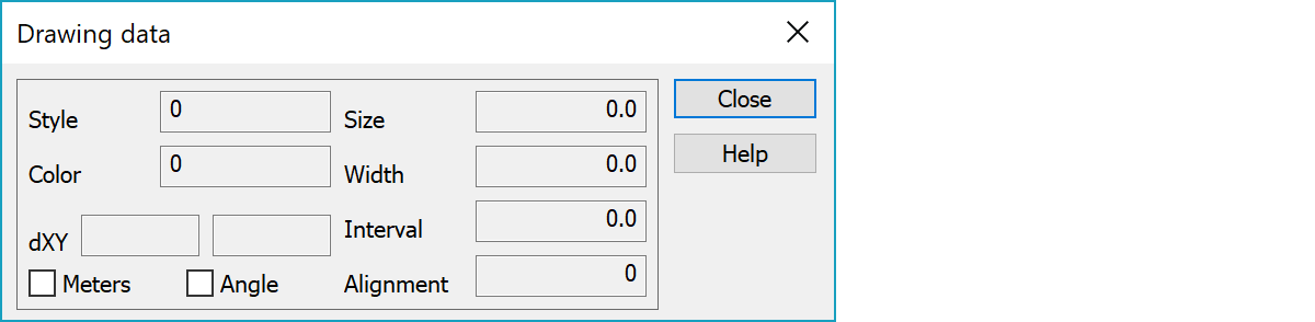
Object drawing data can be used to override code file drawing rules for specific objects.
Symbol id, line drawing style or area hatch pattern.
Color used for drawing. Can be given either as a color table index 1-30 or as a real RGB value.
Text offset values which are added to the actual text coordinates. If the Angle setting is on, offset values affect in text direction and the parameter order is always AB (A horizontal and B vertical to the text direction) regardless of used units. If the Angle setting is off, offset values affect in axis direction. If the Meters setting is on, offset values are in meters and their order is same as file coordinate order (usually X to north and Y to east). Otherwise values are in millimeters and they use always mathematical order. Switching checkboxes changes the values using current paper scale.
Text or point size. Positive value is in millimeters and negative value in meters. For texts value zero uses label size from the point view settings.
Line width. Positive value is in millimeters and negative value in meters.
Area hatch line interval. Positive value is in millimeters and negative value in meters.
Text alignment position according following picture:
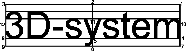
Value 15 means single line numeric value alignment to the decimal point. This works in screen and printing, but is converted to value 5, when transferred to other systems.
For points this affects point view label displaying.