Autocad DXF-files.
If the code file is given, converter writes also colors, symbols and line types in given scale. Symbols are defined as blocks named by feature code (T3). If a block name if defined in the control file, it will be used , but the block data is coming from the code file.
If the text size is positive (given in millimeters in 3D-Win), it will be multiplied by 0.8, to get the same size in DXF-file. This is because of the differences in font cell definitions.
Format header file can contain macros and file attributes.
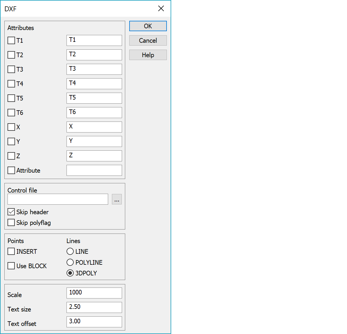
If the last item Attribute is selected, all attribute in DWG-file are copied to the point as attributes. If you have defined and selected any other item, it will be converted as code field (T1-T6) or coordinate. A converted attribute does not remain as normal attribute. This way you can read a PNO-named attribute into point number (T4). If the last item (Attr.) is not selected, the attributes can be converted into code fields/coordinates, but no normal attributes will be with the point.
Input attribute name to store the original layer name. If you define the same attribute in Write-function, the original layer name will be written. The same feature can be found also in some other formats.
Select the code fields to be written as attributes in DXF-file and define a name for the attributes. You can not rename the normal attributes here. An empty value will not be written in DXF-file.
Point, which have attributes and shall be written to DXF-format, must have a symbol defined in the code file. If you have selected any attributes here, the break lines are copied as single points, because break lines (or points on a break line) can not have attribute data in DXF-format. If you need to have a fixed block name, use DXF.LAY-file to define line having feature code (T3), layer name and block name. See also Text size and text offset.
If text alignment (justification) is 5 and text has a decimal point, the text will be written in two parts to get decimal point precisely on the XY-point. This applies only horizontal texts. See also Special setting SkipTextDivide.
Control file determines layer coding. Feature code of a point, line or text is converter into layer name or vice versa.
Skip DXF-file header block in other words all lines before ENTITIES-line.
Do not use the PolyFlag-value (POLYLINE-element) to create lines.
INSERT writes single points as INSERT points. Use BLOCK uses blocks defined in control file. No effect, if the code file is used.
Line entity selection. Possible one point lines are converted into single points before output.
Scale used for text, symbol and line type scaling.
Attribute text size and attribute spacing in meters. Spacing must be used if an object has several attributes.
Because an attribute in DXF-file is visible (like a text), you can define also text size and offset (line spacing). Default values: size=2.5, offset=3.0.
Control file determines layer coding. Feature code of a point, line or text is converter into layer name or vice versa. Following definitions can be given:
Object code in 3D-Win (T3). The first code is default code.
Layer in Autocad. Layer name can be macro #CODE_T3, which means that the code explanation from codefile is taken as layer name.
Combination of following options:
0 all objects
1 only points
2 only lines
4 only texts
Block name. Block name can be macro #SYMBOL, which means that the symbol code from codefile is taken as block name.
This value controls what attributes this code will have. It is a binary sum, which defines code fields/coordinates/attributes to be written in DXF-file as attributes. If you have defined Attribute control in More-dialog, they will owerride these settings. Because in a DXF-file an attribute is like a text, you can define text size and offset in More-dialog.
1=T1-field
2=T2-field
4=T3-field
8=T4-field
16=T5-field
32=T6-field
64=X-coordinate
128=Y-coordinate
256=Z-coordinate
512=all attributes
Free comment
!    code  layer          opt     block       comment
       0   Def_layer       3       3D         //
       1   L1              0       B1         //
       2   L2              0       -          //
       3   L3              0       B3         //
     C90   90              1       B90        //
     120   120             1       BX20       //
     121   Point121        1       B121P      //
     121   Line121         2       B121L      //
     122   Layer122        1       B122P      //
     123   Layer123        2       B123       //
     140   Layer140        2
There are some special settings related to this converter.
A list of feature codes (T3-field) which will be skipped in DivideText.
Removes same texts too near each other.
Writes a break lines as POLYLINE-type with a definition "Inserted by curve fitting".
Skips layers not defined in control file.
See also: Common special settings